1
2
3
4
5
6
7
8
9
10
11
12
13
14
15
16
17
18
19
20
21
22
23
24
25
26
27
28
29
30
31
32
33
34
35
36
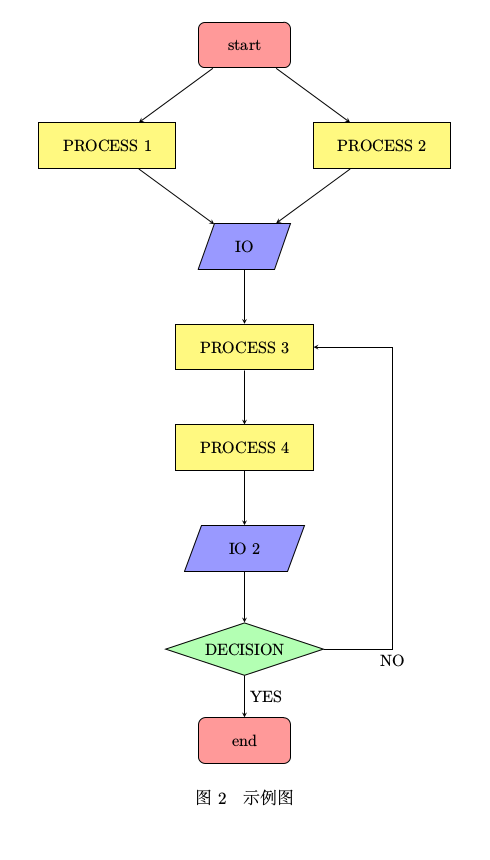
| % 流程图定义基本形状
\tikzstyle{startstop} = [rectangle, rounded corners, minimum width = 2cm, minimum height=1cm,text centered, draw = black, fill = red!40]
\tikzstyle{io} = [trapezium, trapezium left angle=70, trapezium right angle=110, minimum width=2cm, minimum height=1cm, text centered, draw=black, fill = blue!40]
\tikzstyle{process} = [rectangle, minimum width=3cm, minimum height=1cm, text centered, draw=black, fill = yellow!50]
\tikzstyle{decision} = [diamond, aspect = 3, text centered, draw=black, fill = green!30]
% 箭头形式
\tikzstyle{arrow} = [->,>=stealth]
\begin{figure}[htbp]
\centering
\begin{tikzpicture}[node distance=2cm]
%定义流程图具体形状
\node (start) [startstop] {start};
\node (pro1) [process, below of=start, yshift=-0.2cm, left of=start, xshift=-1cm] {PROCESS 1};
\node (pro2) [process, right of=pro1, xshift= 4cm] {PROCESS 2};
\node (in1) [io, below of=pro1, yshift= -0.2cm, right of=pro1, xshift=1cm] {IO};
\node (pro3) [process, below of=in1, yshift= -0.2cm] {PROCESS 3};
\node (pro4) [process, below of=pro3, yshift= -0.2cm] {PROCESS 4};
\node (in2) [io, below of=pro4, yshift= -0.2cm] {IO 2};
\node (dec1) [decision, below of=in2, yshift= -0.2cm] {DECISION};
\node (stop) [startstop, below of=dec1] {end};
%连接具体形状
\draw [arrow](start) -- (pro1);
\draw [arrow](start) -- (pro2);
\draw [arrow](pro1) -- (in1);
\draw [arrow](pro2) -- (in1);
\draw [arrow](in1) -- (pro3);
\draw [arrow](pro3) -- (pro4);
\draw [arrow](pro4) -- (in2);
\draw [arrow](in2) -- (dec1);
\draw [arrow](dec1) -- ($(dec1.east) + (1.5,0)$) node[anchor=north] {NO} |- (pro3);
\draw [arrow](dec1) -- node[anchor=west] {YES} (stop);
\end{tikzpicture}
\caption{\label{fig: } 示例图}
\end{figure}
|